| Edidoom : Intel Edison based video game console playing Doom |
|
|
|||||||
|
The Intel Edison is a tiny system-on-a-chip (SOC), with a 500 MHz dual-core CPU, 1 GB of RAM and 4 GB of permanent storage. It provides plenty of computation power to run older video games, like Doom from 1993. However what the Edison does not have built-in is any display, audio, or game input hardware. So this project was about adding those peripherals with sufficient performance to run a video game. :: Hardware
:: Software The basis for the code is the original Doom source code, which is a port for Linux using X11 as video interface. There are many other ports of Doom, all with bug fixes and improvements since then, but quite frankly I didn't spend the time on investigating the pros and cons of each, and I was also looking for the smallest, simplest version of the code, and feared most "improvements" probably made the code larger and more complex. This decision proved fine so far. There was a little bit wasted effort on bug fixing and a few updates due to newer compilers/LIBC changes, but it was pretty low, especially compared to the hassle of modern build systems and package managers that most source packages have. The main modifications where the video interface (i_video.c), the sound interface (i_sound.c), and the input code (now in i_system.c, used to be in i_video.c, probably due to the X11 interaction). .. Video driver Writing a driver for the display proved to be the largest effort, as no existing software provided fast enough solutions for hooking up this TFT display to the Edison. The starting point was the Arduino example code from Adafruit, described in their tutorial (8-bit wiring version). This together with custom code to quickly set the output pins on the Edison, based on the internals from Intel's MRAA library proved successful. Writing data to the display requires setting 8 data lines to their correct bit value, and then flipping a write signal (WRX) pin from low to high. The fastest way to achieve this is to use memory mapped IO, where in theory up to 32 pins can be set with two 32-bit memory writes, one to clear LOW bits and one to set HIGH bits. The 40 GPIO pins of the Edison aren't tightly packed when it comes to pin indices, and are spread in the range of 12-183. The largest consecutive number of pin assignments is in the 32-63 range, where we can use pin 40-47 as data lines, and pin 48 or 49 as write signal WRX. To cleanly write a data byte, we can do 3 write operations:
We want to get maximum performance, and keep the number of write operations as low as possible. According to the spec of the display controller, it wants us to hold the data lines steady for 10 ns after the WRX toggle for it to read out the data. Surprisingly it "just worked" to not explicitly hold the lines steady and fold the last step, setting WRX to HIGH, together with the first operation of the next write operation. With that optimization we are down from 3 write cycles to 2:
If it wouldn't have worked immediately, it would probably be possible to "slow down" the WRX pin a little, eg with a capacitor, so that it flips in the middle of our data bit write cycles. One other problem happened that I wasn't able to explain though: During development I had a logic analyzer (Salea Logic) hooked up to several pins of the display, while these write operations worked fine. Once I disconnected it, all of a sudden, certain pixel colors would cause stretched out pixels, as if multiple pixels were written instead of one. A problematic color was orange, with 16 bit pattern 0xFC00, which means one byte gets written with a lot of 1's, and the next byte has a lot of 0's. Somehow this must have caused some oscillation or whatever and disturbed the signal. I couldn't debug this with my logic analyzer as obviously its presence made the problem disappear... So I "experimented" to find what characteristic of having the logic analyzer connected causes the system to behave differently. In the end the most reliable fix for this, was placing a 100 Ohm resistor between ground and any of inputs of the display (I used the display's CS pin as it's the least "used" one). Still no idea why this fixes this. Suggestions from someone with stronger electrical engineering knowledge would be appreciated.
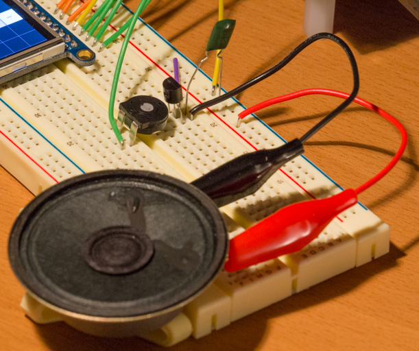
The resulting performance ended up at 64ms/frame for updating 320x200 pixels, with about 67ms/frame for the whole game tick, so about 15 frames per second. As described above one byte needed 2 bus write cycles, and one 16-bit pixel needs two bytes, so a total of 4 bus write cycles, and those seem to be limited to 4 MHz. I experimented with getting faster bus speeds from the Linux kernel, instead of through the memory mapped IO from user space, but the speeds came out to be the same. There does not seem to be hardware documentation about the GPIO device in this chip, the most details are in Intel's Linux kernel patch for the Edison in gpio-langwell.c. From all I can tell there does not seem to be a configurable bus speed, or a mode to set and clear bits with a single bus operation. The only hope I have for driving the display at higher rates, to achieve 30 frames per second, is to use the display with a 16-bit bus. The display controller can actually read 16-bits in a single operation, but 8 of those data lines are not exposed on the Adafruit breakout board. Unfortunately the Edison does not have 16 GPIO pins in a single 32-bit memory register, so even with custom hardware this would still require two separate pin region updates, which would not be faster than 2 consecutive 8-bit writes. As an experiment though, I enabled 16-bit mode, while still only have access to 8 data lines, which leaves 8 of the 16 bits permanently 0. It works! By doing this we can write monochrome blue pixels at twice the data rate, and render at 30 frames per second! Doom only renders with an 8-bit palette, so it can only render 256 distinct colors, and it would be possible to find 3 RGB gamma curves to trick the display to create different colors out of our single set of 8 data lines that would be close to the desired palette. An exercise for the future. .. Sound output Like most Arduino-ish systems, the Edison does not have an analog output pin. It has analog inputs, but only digital outputs, that can be at full voltage or 0. For decent quality sound output, basically anything beyond a square wave at a fixed amplitude, a smoothly rising and falling voltage is necessary. A good overview of available options is in this Arduino-focused article. The two most promising approaches for my application seemed to be a smoothed out pulse width modulated (PWM) signal or a resistor ladder. A resistor ladder uses multiple digital pins with effectively varying resistors each, thereby representing a different bit of a discretized signal that can be added together to approximate a continuous signal. I could probably afford to use 4 or 5 digital pins for such a system, leading to 4- or 5-bit sound signal, which would still have pretty significant steps between neighboring values, and should be smoothed out with a low pass filter.
Therefore it seemed simpler to start with a single PWM signal with a smoothing filter, and add more bits later if necessary. The Edison hardware is capable of generating PWM signals at up to 1 MHz frequency, with varying duty cycle. Doom uses 11025 8-bit samples per second, so with 1 MHz approximately 100 different voltage levels could be represented if an ideal filter existed. This Make magazine article describes practical hardware setups for a PWM with low pass filter and a transistor for amplification. I derived some good values for capacitor and resistor for my low pass filter with this handy online calculator. For a 1 MHz PWM frequency with good data representation up to 11 KHz, a capacitor with 10 nF and a resistor of 1 KOhm seemed appropriate. I ended up using a 1 KOhm potentiometer resistor instead to be able hand tune the optimal behavior. It now mainly functions as a volume selector. Despite all these calculations, using a PWM frequency of 100 KHz proved to give higher audio quality than 1 MHz. Not exactly sure why, my suspicion is that the duty cycle setting of the PWM signal has limited time duration precision as well, and with lower overall PWM frequency, more duty cycle values can be represented. .. Bluetooth controller input Hooking up the PS4 controller turned out to be relatively easy. The Intel Edison Bluetooth Guide describes initiating pairing of a Bluetooth input device (Chapter 6.1). Once the Edison Bluetooth chip scans for devices, the PS4 controller needs to be started by pressing the Share and PS button together until the front light start flickering quickly. The controller's device ID should show up on the Edison in bluetoothctl, and then can be paired ("pair [DeviceID]"), trusted ("trust [DeviceID]") and connected ("connect [DeviceID]"). Unfortunately, I have not figured out how to store these settings permanently on the Edison. The Linux Bluetooth stack documentation is notorious for not existing. Currently at a minimum after boot up, I have to unblock the Bluetooth device, and trust the controller ID, which will allow it to connect when turned on. Once the PS4 controller is connected, it can be read via /dev/input/event2. The evtest utility mentioned in Intel's guide worked excellent to dump the various key presses and axis changes. For now, I've only hooked up the left stick and the four digital symbol buttons to Doom's joystick event, even though that one assumes a "digital" joystick in the classic sense, where each axis can only be fully extended or centered. Mouse events in Doom allow analog movements and would be more suitable to the analog sticks of the PS4 controller, but I haven't spent the time for finding a nice analog mapping curve between these devices yet. :: Putting it all together I hope the above descriptions are sufficient for anyone to recreate this setup. The source code repositories below are projects for the Eclipse workspace of Intel's IoT Developer Kit. Just import (File/Import/General/Existing Projects into Workspace...) them into the examples workspace, create a new Debug configuration for the project using the Edison connection you've set up in the Remote System Explorer and run. You will need a WAD file (the game data) from Doom to run it. One option is to download the shareware version of Doom from idSoftware's FTP server. Then run the installer in DOS, eg via DOSBox. Copy the resulting "doom1.wad" file to the Edison. Doom searches the home directory "/home/root" for WAD files, so just put it there. Make sure the filename is all lower case, it might be upper case when copying from DOS. For the hardware setup, the exact wiring of the display data lines can be found in the source code (in "edidoom/src/i_video.c" or "edison-graphics/src/Adafruit_TFTLCD/Adafruit_TFTLCD.cpp"). The sound output hardware described above is hooked up to Arduino pin 3. :: Source code Edidoom: Source code for Doom, including the sound and display drivers. Display driver code and test program: Contains both a version for the SPI interface and the parallel interface described above. The SPI version should still work (even though it hasn't been run recently), but performance was clearly not good enough for animated rendering, approximately 2 seconds per frame. Audio driver code and test program: Plays a sound sample continuously, either in the main thread or a worker thread while simulating various workloads in the main thread, to prototype the eventual use case inside the Doom source code.
For further information contact: Lutz Latta (llatta at 2ld.de) <Last update: 8 February 2015> |
|||||||